
Optics - Birefringence
ESPECIALLY FOR OUR USERS
Optical components made of plastic are often used in the photoelectronics, 3C and automotive industries as a replacement for conventional glass materials due to their good price-performance ratio and applicability.
With the growth of the plastics industry, optical components such as discs, lenses and waveguides are increasingly manufactured using injection molding. In the development of optical parts, one of the most important factors is the birefringence caused by molecular alignment during injection molding, which leads to optical anisotropy.
Birefringence is the splitting of a light beam into two beams when it passes through transparent materials. When polarized light passes through these materials light and shadow stripes are created, the size of which depends on the difference in the main voltages.
Birefringence in optical parts is mainly caused due to two reasons. One is flow-induced residual stress, which is due to molecular alignment during filling. The other is thermal residual stress, which is due to disequilibrium contraction during cooling. The flow-induced residual stresses are generated by the high shear rates during filling and can be relaxed or frozen during the holding pressure phase and after ejection. Thermally induced residual stresses are caused by different temperature levels and by shrinkage below the glass transition temperature Tg. In order to better control birefringence, various methods have been developed to investigate birefringence phenomena both numerically and experimentally. In numerical approaches, the conventional 2.5D simulation cannot provide a promising prediction of birefringence due to the inherent assumptions and model simplification through the construction of the middle plane.
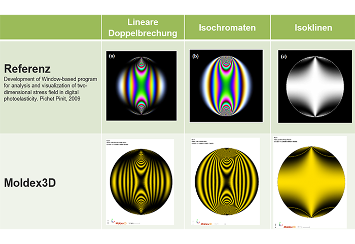
Consequently, a true 3D numerical approach to these circumstances is in high demand. The Moldex3D Optics module therefore allows the user to observe crucial factors within an optical component, such as birefringence, retardation and fringe patterns.
High mesh quality is required for optical simulation, which is why it is strongly recommended to use hexa or prism elements for mesh generation and the mesh plane in the thickness direction should exceed 8 layers. Only solid meshes are supported.
Additionally, the material used in the optical analysis must have optical properties. Please make sure that you have selected the correct material before conducting an analysis. Furthermore, the results of filling/packing, cooling and warpage are required in order to use the optics module. Optical components that are injection molded in multiple layers can also be analyzed using Moldex3D for flow-induced and thematically induced residual stresses.
If you have any questions about using the module, our team will be happy to help!
Please contact us: 0241 565 276-0 or send an email to sales@simpatec.com.