Holistic Product Development of a Carbon Fiber-Reinforced Bicycle Frame
Plastic Innovation GmbH is taking a new approach to the economical and sustainable development of bicycle frames with carbon fiber-reinforced plastics. In the conception of functionally integrated and injection mold-ing-appropriate designs, SimpaTec supports the company with up-to-date simulation expertise. The frame of the first fully functionable demonstrator, an e-bike with a challenging low-entry design is manufactured fully automatically in a cycle time of 90 s by the WAIM method.
The development of the first bicycle is more than 200 years old. Even if this vehicle does not have much in common with modern ones, the bicycle has written an unparalleled success story during the last years thanks to the e-bike boom. In Germany alone, about 4.7 million cycles were sold in 2021 – two million of them e-bikes. This development has changed the industry. Due to the integration of battery and motor, combined with a sleek styling, e-bike frames are becoming ever more complex and correspondingly also costlier to manufacture.
The market is generally undergoing a dramatic transformation. Bicycle frames for the mass market are usually made of aluminum. However, the increasing social awareness for sustainable products with reduced energy consumption in manufacturing, logistics and operation has led to attempts to re-evaluate the products of the future and improve their efficiency [1]. The choice of the production site, manufacturing process and material are key factors in achieving these goals. Injection molding of short fiber-reinforced thermoplastics thus allows structural parts to be manufactured in a large number of industries, including applications of so-called micromobility, such as e-bikes, e-scooters and the like. Simulation tools play an important role here - they can be used, e.g., to design cycle frames for injection molding. Thanks to digital product development methods, complex processes, too, can be simulated and represented in order to support the developers. And all at a time before a single chip has been machined.
Defining the WAIM Cavity already in the Development Phase
While powerful electric motors are increasingly raising the technical requirements for bicycle frames, plastics are ideally suited for integrating the drive technology in an attractive design. With the Ecobike1 model, V Frames is presenting the first fully functioning demonstrator as an e-bike in a challenging low-entry design. Its frame is made of a polyamide 6 reinforced with 40 % carbon fibers (type: Akroloy PA CDF VFrame; manufacturer: Akro-Plastic).
To be able to realize the normal tubular structure – a prerequisite for the necessary torsional stiffness of the frame – the WAIM process (water assisted injection molding) is used. This is a two-phase process. Taking the bicycle frame as an example, this means that the part cavity is completely filled first, as in a conventional injection molding process. During this filling procedure, the overflow cavity and water injectors remain closed. After filling, the overflow cavities and water injectors are opened. In the second phase, the inflowing water forces the still liquid melt core into the now open overflow cavities. The cavity thus created in the part is then blown dry.
The aim is to define this cavity as precisely as possible already during the development phase. Additionally, to filling the cavity with polymer and water, both the orientation and distribution of the fibers in the polymer must be considered. The frame stiffness and the riding dynamics depend strongly on the residual wall thickness, the fiber orientation, the weld lines and their distribution along the structure. At this point, it is already clear that the results of the filling simulation must be taken into account in the product development.
Comparison of the Residual Wall Thicknesses from Simulation and Measurement
For the simulation of the WAIM process, Plastic Innovation GmbH, Ottensheim, Austria, used Moldex3D. To accurately simulate the pseudoplastic behavior of the plastic and the complex WAIM process, it is necessary to have a good resolution at the outer layer. Only so can the influence of the shear velocity on the pressure profile and temperature distribution be accurately predicted during filling. At the same time, the meshing in the core for the water channel must still be sufficiently accurate. The BLM technology (boundary layer mesh) was developed for this purpose. High-quality meshes can be easily and reliably generated. The mold design and cooling channels were generated using the Moldex3D wizard. In so doing, the mold can be included in the simulation at an early development stage and later be transferred to the design.
An important assessment criterion is whether the simulation is able to precisely predict the wall thickness distribution. For this reason, a comparative study was subsequently performed. The cross-section was measured at two positions on the lower tube, at four points in each case, and compared with the simulation (Fig. 1). The average values and their standard deviations compared to the simulation show a similar trend for the data at measurement positions 1 to 4 (Fig. 2). The calculated wall thicknesses in the simulation correspond to reality with sufficient accuracy. It is important that larger wall thicknesses are implemented in reality than are predicted in the simulation. For further developments, this finding means that no further safety factors for the fluctuation width need to be taken into account.
Case study e-bike frame
Drop by Drop
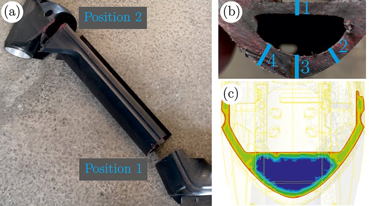
Fig. 1. a) Cutting positions of the lower tube for wall thickness measurement; b) marking the four measurement positions over the cross-section of the lower tube; c) one of the simulated hollow part cross-sections. © Post-doctoral thesis U. Cakmak
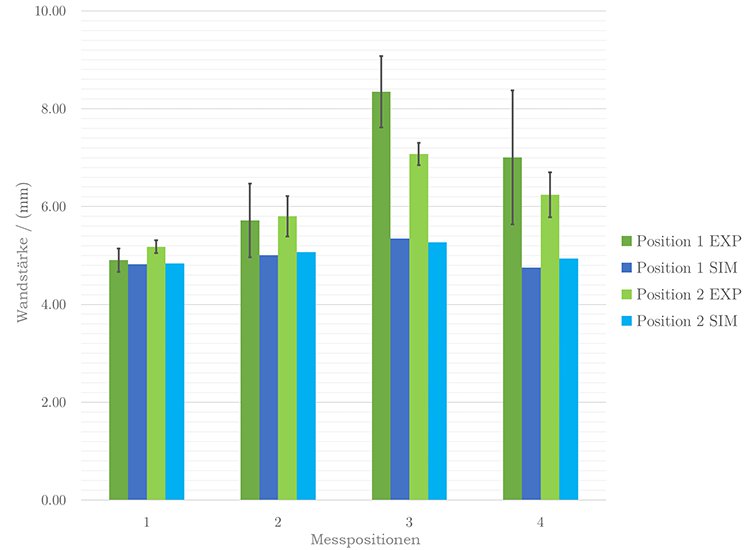
Fig. 2. Comparison of the experimental and simulated wall thicknesses at the four measurement positions of the frame lower tube. Source: © Post-doctoral thesis U. Cakmak
Integrative Simulation: Avoiding Unnecessarily Large Safety Factors
Due to the process simulation with Moldex3D, possible processing instabilities, as well as defects (e.g., weld lines, water fingering, uneven wall-thickness distribution and fiber orientation) are identified and eliminated. Based on these results, a finite element analysis (FEA) was performed. For this purpose, the simulated water channel was exported as an STL file and imported into the FEA. With other products, too, it is advisable to include this information in the FEA, so that there is no need to incorporate unnecessarily large safety factors.
Safety factors always mean that a product must be designed with thicker walls than would have been necessary for the intended use. This not only requires more material but also the unnecessarily prolonged cycle times due to the process. If the results from the process simulation are included into the structural mechanics, the term “integrative simulation” is used.
Plastic Innovation even went one step further in the development of the bicycle frame. The company opted for a holistic product development approach. In addition to the "integrated simulation", they also considered tool design and automation. The requirement (on behalf of the customer) with regard to automation lay in a constant, efficient cycle time for the following work steps -. Placing the frame being removed from the injection molding tool onto the conveyor belt and picking up the aluminum head tube insert and insert it into the tool. These steps are carried out by the producer V Frames GmbH.
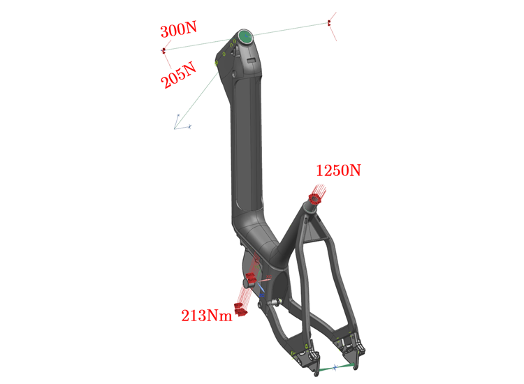
Fig 3. Different loads acting on the cycle frame complement each other to form the load case. © SimpaTec
Closing the Gap between the Manufacturing Process and Structural Mechanics
For the FEA, the test was based on EN 15194:2018:11 (cycles – electrically power assisted cycles – EPAC bicycles). This test was also performed on the final cycle frame after the development was completed. To pass the test, the cycle frame must not break after multiple cyclical loads. The load case is composed of a pedaling torque of 213 Nm, a seat load of 1250 N and vertical and horizontal loads of 300 N and 205 N, respectively on both sides of the dummy handlebar (Fig. 3). The frame is fixed in two positions, firstly on the rear axle, and, secondly, the dummy fork was attached in both vertical and lateral directions, which means that rotation as well as axial displacement remain unrestricted (Fig. 4).
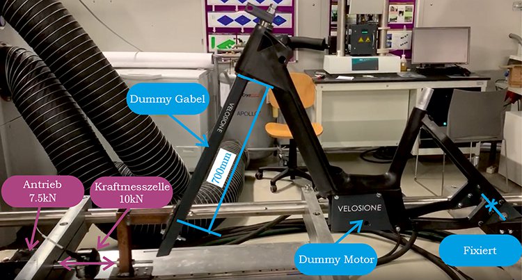
Fig 4. Measurement setup during the load test. © Post-doctoral thesis U. Cakmak
The software Marc was used for the FEA. Marc is the ideal solution, particularly for nonlinear systems, as with this cycle frame, but also for all other plastic products. To close the gap between the manufacturing process and structural mechanics, multiscale material modeling, including the interface to FEA with Digimat is used. This material modeling technology allows to simulate the complex anisotropic material behavior as well as damages.
In order for Digimat to calculate the realistic material behavior, simple, standardized material measurements are sufficient to transfer them to the complex component. Digimat and the FE solver communicate with one another and exchange data about both the material behavior and the loading situations. This makes it possible to consider process-related properties such as fiber orientation, weld lines and residual stresses in the simulation.
To facilitate the evaluation and interpretation of the results, Digimat offers additional result plots. The anisotropic material behavior can thus be represented in the form of indicators and utilization rates. The simulation could thus correctly predict that the cycle frame will pass the test according to EN 15194:2018-11. In addition, the component behavior could also be considered in detail with respect to the complex material behavior.
A Matter of Interpretation: Resilient, but Light
The consideration of von Mises stresses (Fig. 5) is a common method of assessing the stress distribution. However, this method only has limited application because of the anisotropy. With respect to the cycle frame, it can be seen that the stresses lie in the non-critical range. If the result is compared with other result plots offered by Digimat, an even more comprehensive and better assessment of the cycle frame is obtained, and more accurate statements can be made.
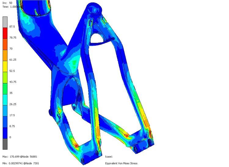
Fig 5. There are limits to using stress distribution by means of von Mises stresses due to the anisotropy. © SimpaTec
Based on the utilization rate of the maximum stiffness (Fig. 6), the critical areas can be quickly and easily determined. Failure occurs at a utilization level above 1. All ranges below 1 show corresponding safety.
The degree of utilization of the fibers in terms of their orientation is also an essential aid to better assess whether it is necessary to improve the fiber orientation in certain areas.
The degree of utilization of the fibers in terms of their orientation is also an essential aid to better assess whether it is necessary to improve the fiber orientation in certain areas.
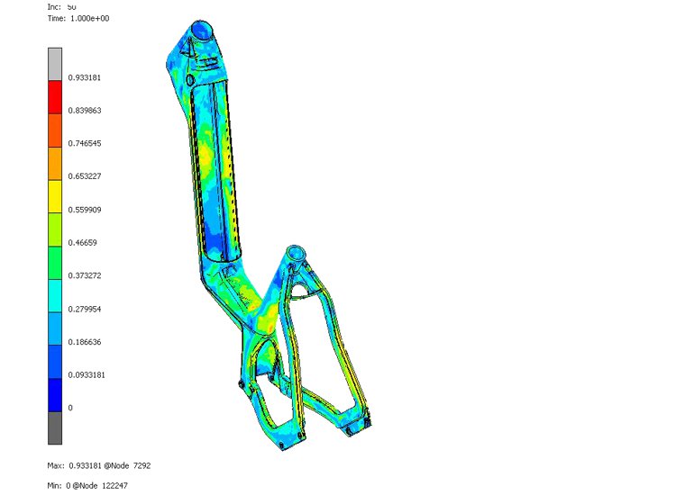
Fig 6. The utilization degree of the maximum stiffness identifies the critical areas. © SimpaTec
The degree of utilization of the fibers in terms of their orientation is also an essential aid to better assess whether it is necessary to improve the fiber orientation in certain areas.
To assess the influence of the weld lines, knockdown factors are taken into account in the simulation. Depending on what properties the weld line has, this locally permissible stress is reduced. For the question of how the load case affects the local material stress, the result from triaxiality is helpful, so that it is possible to distinguish between tensile, compression, shear and biaxial load states. All these results make it easier to design the part so that it can withstand the stresses but still be as light as possible.
Positive Life Cycle Assessment with Recycled Carbon Fibers
The substitution of metals by thermoplastics also opens up new recycling strategies. The best strategy consists in using recycled materials for structural instead of non-structural components or other purposes (thermal recycling, landfill). A life cycle assessment (LCA) was also performed for the cycle frame. A comparison was made of the effect of changing from aluminum 6061 T6 to a polyamide reinforced with recycled carbon short fibers.
The LCA is based on the CML method, a multidimensional approach to life cycle assessment that was developed at the Centrum voor Milieukunde in Leiden, the Netherlands (CML). The characterization and normalization of the impact categories was performed with the software GaBits 10.6 at the energy institute of Johannes Kepler University, Linz. A functional unit (comparative quantity, 36 bicycle frames) was defined for the comparison. Raw material procurement and production up to transport were evaluated. The prerequisite was that the cycle frames can be manufactured with equivalent structural properties from both materials. In this analysis, the global warming potential (GWP, based on a period of 100 years) found that the CO2 equivalents (per functional unit) of aluminum frames are 1604.64 kg CO2 eq. and those of polyamide are 444.4 kg CO2 eq. This means that when the bicycle frame is made of polyamide with recycled carbon short fibers, a CO2 reduction of approximately 70% is possible.
This innovative manufacturing process has since proven its worth. Plastic frames with stiffness and weight comparable to aluminum frames have been optimized to such an extent that they are suitable for mass production while at the same time being energy-efficient and sustainable.
Authors
DI Dr. Umut Cakmak is managing director of Plastic Innovation GmbH, Ottensheim, Austria, and Senior Scientist at the Institute of Polymer Product Engineering at Johannes Kepler University Linz, Austria
Cristoph Hinse is CEO of SimpaTec Technology Consulting GmbH, Aachen, Germany
Tobias Schäfer, M.Sc., formerly R&D Engineer at SimpaTec Simulation & Technology Consulting GmbH; Aachen
Ing. Florian Aichberger, M.Sc., is Sales Engineer at SimpaTec GmbH in Austria
Acknowledgments
The authors would like to thank the companies involved for their support:
_ V Frames GmbH: injection molding tool, automation and production
_ Coleo Design GmbH: Conception and design
_ Johannes Kepler University Linz – Institute of Polymer Product Engineering: simulation and testing
_ Engel Austria GmbH: machine manufacturer and applications technology support
_ Akro-Plastic GmbH: material manufacturer and applications technology support
_ Plastic Innovation GmbH: product development & simulation
Copyright
_ Moldex3D is a registred trademark of CoreTech System Co., Ltd., Taiwan.
_ Marc and Digimat are registered trademarks from Hexagon AB, Stockholm, Schweden.
Englisch Version was first pusblished in Kunststoffe International 08/2022.
