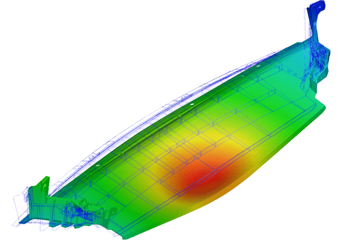
Buckling of injection molding parts and how to simulate it
ESPECIALLY FOR OUR USERSMost parts produced by injection molding are either completely or in parts two-dimensional or one-dimensional in nature. In other words, they have wall thicknesses which are smaller compared to the other dimensions (two-dimensional) or they contain slender structures with a cross section dimensions which are small compared to their length (one-dimensional). Structures of this kind (and this applies not only to plastics) are susceptible to buckling (stability failure). Therefore, prediction of buckling failure can be of interest.
Buckling can be described as a sudden change in the deformation after reaching a critical load. This means that near a critical load level a small increase in loads leads to a large deformation. Along with the geometrical prerequisites, a s mentioned above, compression stresses are required for buckling to happen – a structure exposed only to tension loads, cannot fail in buckling.
Buckling is a stability problem. Stability problems in structural mechanics can categorized under several aspects
_ Type of buckling (one some important are listed here)
_ Column buckling (sudden bending of a one-dimensional structure under axial compression load)
_ Flexural-torsional and Lateral-torsional buckling (torsion of a one-dimensional structure under a bending load often combined with a deflection perpendicular to the load direction)
_ Plate buckling (out-of-plane deflection of a two-dimensional structure under in-plane loads)
_ Extend of buckling
_ Global buckling (the whole part is affected)
_ Local buckling (only a localized area of the part is affected, for example buckling of a rib or buckling of a skin field enclosed by stiffeners)
_ Post-tbuckling behavior
_ "good-natured behavior (the structure is able to carry the applied load after buckling, partly without suffering permanent damages)
_ "ill-natured" behavior (buckling leads to a collapse of the part accompanied with loss of functionality and permanent damages)
Specifically, for injection molding parts an additional aspect should be considered, namely what the production process itself can lead to buckling. In this case the residual compression stresses after the ejection (and cool down) of a part lead to buckling, causing deviations from the intended part geometry which can be much larger as caused by warpage and shrinkage. To assess the danger of buckling caused by the injection molding process, Moldex3D provides since the version 2021 the option to perform a linear stability analysis additionally to the warpage analysis.
The linear stability analysis is the most used simulation method to compute buckling. Virtually all widely used FEM structural solver have this analysis method implemented. Every of these solvers can be used to predict buckling of a part due to external loads, which can be expected in the lifetime of this part. The biggest advantage in of the linear stability method is the relatively high computation speed. It is especially advantageous if a lot of load cases have to considered. The reason is what the stiffness is independent of the load, so the structural stiffness matrix of the part has to be computed only once and is valid for all load cases. But as a user, one has to aware of the disadvantages of the linear stability method:
_ Only linearelastic material model can be used, meaning all material non-linearities are neglected
_ Only two types of results are produced:
_ The critical load factor and derived from in the critical load level (which is the product of the critical load factor and all the applied loads).
_ The buckling form. Here it is important to understand what the overall buckling form is computed correctly, but the absolute deformation values are normalized against an unknown basis. Therefore, no derived results (stresses, strain, damage indicators) can be computed correctly.
In summary, the linear stability analysis only produces results associated with the critical stability point itself. Nothing can be said about the behavior below the critical load lever or about the post-buckling behavior. It cannot ever predict if the post-buckling behavior will be “good- or “ill-natured”. This is especially important in case of “ill-natural” post-buckling, since in these cases linear stability analysis can over-estimate the critical load level considerably.
To avoid all the uncertainties associated with a linear stability analysis, a non-linear static analysis has to be performed using a FEM structural solver which able to perform this kind of calculation (for example MSC Marc). Using a non-linear analysis in scenarios with a “ill-natured” post-buckling behavior the critical load level can be predicted more precisely. And for scenarios with a “good-natured” post-buckling behavior it can be computed how much more load beyond the critical level the part is able to carry and predict damages in the structure in the post-buckling regime. Also, the material non-linearities, which are especially important for plastics, can be considered. But, like in all non-linear methods, these advantages are contrasted by considerably higher computational times and by higher preparation effort.
For further information please contact us at 0241 565 276 0 or send an email to info@simpatec.com.
