
Consideration of the nozzle zone in the blink of an eye
ESPECIALLY FOR OUR USERS
You have been confronted with filling pattern or pressure differences between simulation and reality? One possible cause is the neglect of pressure loss and shear effects in the screw clearance volume. In our article we will explain how you can effortlessly take the nozzle zone into account using Moldex3D 2021 …
The flow behavior in the cavity is significantly influenced by the history of the melt in the gating system and the injection unit. It is therefore essential to consider the gating system in order to represent the real conditions in the simulation. To further increase the accuracy of the filling simulation, the additional consideration of the screw clearance volume is recommended, but manual modeling is often time-consuming and complicated. For efficient modeling, the nozzle zone wizard is now available in Moldex3D 202. The user is able to add the geometry of the nozzle zone and the screw clearance volume in ‘a blink of an eye’.
A fundamental requirement to use the nozzle zone wizard is the activation of hexahedron-based meshing for line-based elements in the Studio settings.
The modeling of the components and the gating system, which can be set up based on lines or 3D geometries, is analogous to the conventional method of working. However, the definition of the melt entry is not necessary in this case, as it is automatically assigned as part of the nozzle zone creation.
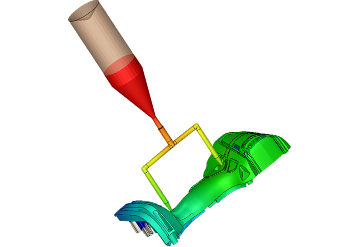
After part and gate modeling, the geometry of the nozzle zone and that of the screw clearance volume is defined using the nozzle zone wizard. The nozzle wizard interface allows you to determine the starting point to which the nozzle zone to be created is to be attached to the sprue system. In the wizard, 3 individual templates are available for the geometry of the nozzle zone and the screw clearance volume, resulting in a total of 9 possible combinations.
The generated, line-based segments for the nozzle zone and the screw clearance volume can be modified by the user totally flexible. This allows the individual adaptation of the segments to reflect the real, geometric conditions. For successful meshing and calculation, it must be ensured that the diameters at the transitions of the segments are continuous and that the diameter of the nozzle tip is smaller than the input diameter of the gating system. Unlike when creating a model without a nozzle zone, the mold block must be created in such a way that it is flush at the transition from the nozzle zone to the gating system.
Machine modes 1 and 2 are available for process definition. In the machine data base, the user can select an already available injection molding machine or create a new machine. The screw diameter and stroke of the selected machine must be consistent with the model.
In the simulation, the melt behavior is not only considered and calculated in the gating system and the cavities but also three-dimensionally in the modeled screw clearance volume and in the nozzle zone. The results thus provide additional insights, for example, into pressure loss and the shear effects introduced in the machine nozzle, enabling the user to optimize the future or existing injection molding process even more extensively virtually.
Deeper insights are of interest!
Please contact us: + 49 (0)241-565 276-0 or send us an email to info@simpatec.com.