
Reduce weld lines by means of SVG
ESPECIALLY FOR OUR USERS
Plastic components that have long flow paths, e.g. shock absorbers from passenger vehicles are usually produced with the aid of several injection points and often have weld lines at the points where the melt fronts of the respective gates meet. The use of cascade injection molding offers the possibility to prevent the formation of weld lines. Read more in our article …
The product quality of molded plastic parts is defined for structural components, amongst others by the maximum load capacity or the load case, and for design components the appearance, i.e. flawless surfaces without streaks, sink marks, visible weld lines, etc., plays a very important role. In some applications, the molded parts must fulfil the requirements of both a structure and a design component. If these molded parts also have long flow paths, where a single injection point leads to a short shot as a result of the melt front freezing up, then the cascade injection molding process is the process of choice.
Cascade injection molding uses a hot runner distribution system with needle valve nozzles. Hot runner technology makes it possible, on the one hand, to bridge the long flow paths to the respective gate, which would not be feasible when using a cold runner system. On the other hand, there is no need for post-processing to cut off the cold runner and, in addition, there is a material saving due to the fact that the material remains in the gating system for the next shot. It is important to ensure that the material-specific dwell time, which leads to degradation of the plastic and thus to a reduction in part quality, is not to be exceeded. The individual gates are controlled separately via the valve gate nozzles in order to open the gates sequentially in comparison to conventional injection molding. This sequential opening of the nozzles, also called cascading, hence the name of the process, cascade injection molding, makes it possible to avoid the formation of weld lines or to relocate weld lines to mechanically or optically uncritical component areas. The main difference in the process sequence with cascading is that the individual injection points are only released when the melt front has already flowed over the next injection point, thus suppressing the formation of weld lines.
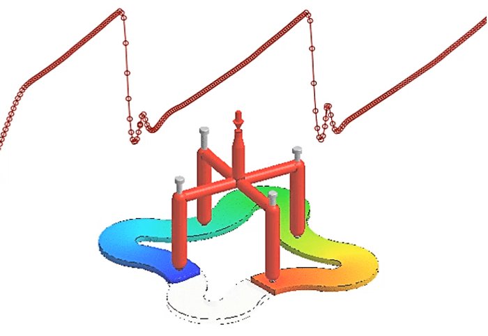
Here, process simulation with Moldex3D Studio offers numerous advantages. Already during the pre-process, i.e. when setting up the simulation model, Moldex3D Studio enables the functionality to carry out the meshing of the hot runner fully automatically without or with a valve gate nozzle. In both cases, the melting chamber of the hot runner is generated considering the dimensions of the valve gate nozzle. This allows the rheological behavior of the melt in the hot runner to be recorded more accurately in order to provide more meaningful results. Various conditions can be determined in Moldex3D Studio for opening the valve gate nozzles. For example, specific mesh node IDs can be defined in the flow direction after the gate, so that the plastic melt of the respective hot runner is released after flowing over the gate point. Furthermore, the ram position and a specific time for the release of the plastic melt can be defined to activate the valve gate nozzle.
By supporting the process simulation with Moldex3D Studio, different sprue manifold designs with different numbers and positions of gating points can be tested and analyzed in order to work out the optimal design of the hot runner and cooling layout already in the mold development phase. Furthermore, the process data from the simulations serve as the basis for the trials on the machine and a much narrower process window can be carried out to achieve the optimum result. This saves very cost-intensive machine time and material waste. If not, all weld lines can be avoided by cascading, these can be visualized via the process simulation and, if necessary, relocated to non-critical part area by optimizing the process parameters. A structural-mechanical analysis following the process simulation as an integrative simulation solution, with consideration of the positions of the weld lines, fiber orientation, etc., in order to assess whether the weld line is favorably or unfavorably positioned in the load case of the later application, is accordingly feasible. The simulation of an adaptive closing and/or opening of the valve gate nozzle for a uniform melt front filling pattern without abrupt pressure drops is also feasible.
Moldex3D Studio enables you to visualize and optimize the cascade injection molding process already in the development phases, in order to save cost-intensive mold iterations, machine times and material waste.
For further information or consulting on the topic of cascade injection molding, please do not hesitate to contact us.
Please contact us: 0241 565 276-0 or send an email to sales@simpatec.com .